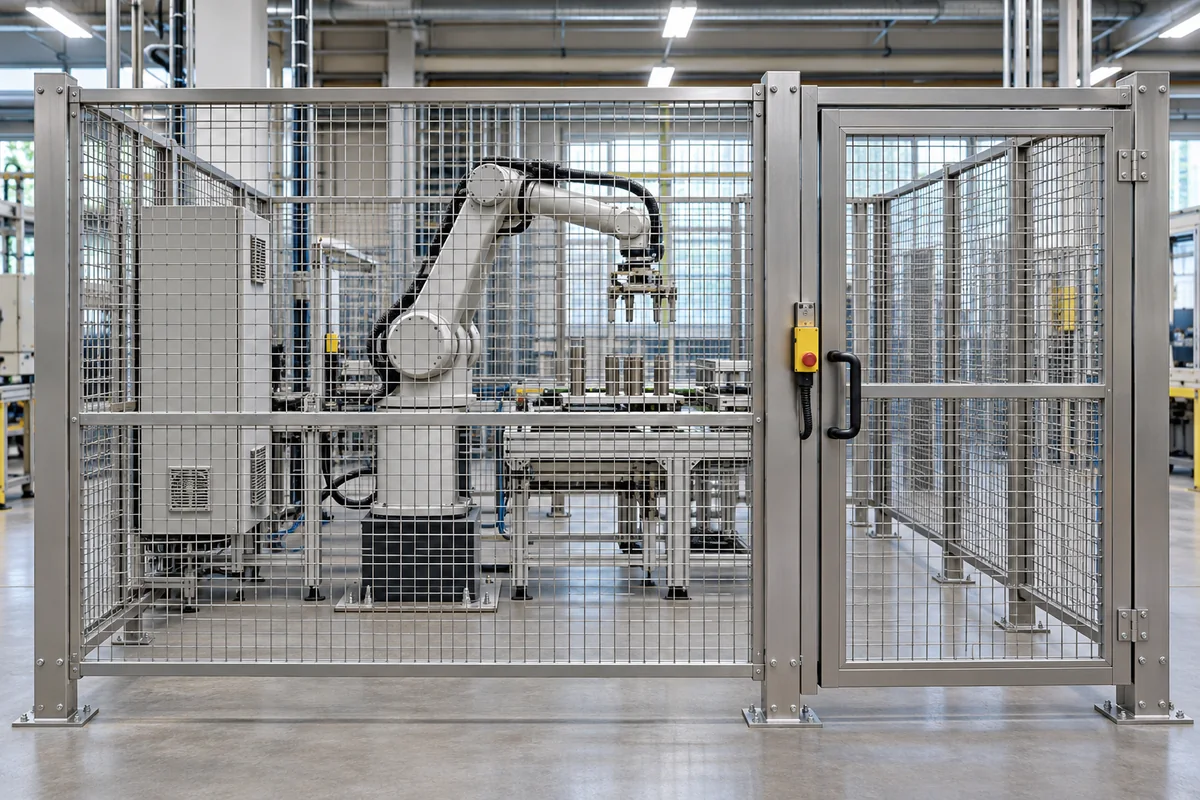
Machine guarding mesh is the open metal infill in a protective enclosure around industrial equipment. Specify it from the machine’s risk assessment, the clear openings in the installed guard and the distance to the hazard. The frame, anchors, access doors and interlocks must work together. Use a different barrier material where the risk assessment calls for containment.
Choose the guard around the hazard
Draw the danger zone first. Mark where operators feed the machine, clear jams, remove product, clean components and change tooling. A mesh perimeter can keep people away from moving equipment while preserving visibility. Where the process throws chips or liquid, the relevant parts of the guard may need a solid or transparent shield designed for the exposure. OSHA’s general machine guarding requirements identify hazards such as rotating parts, nip points and flying material.[1]
| Condition at the machine | Barrier to evaluate | Detail the engineering team should verify |
|---|---|---|
| Visible equipment with a reach hazard | Fixed welded mesh in a perimeter frame | Clear opening, distance to motion, perimeter gaps and attachment |
| Swarf, debris or liquid can escape | Solid, transparent or hybrid guarding | Containment capability, retention and suitability for the projectile or liquid |
| Operators open a gate during normal use | Movable guard with appropriate protective controls | Interlocking, stopping behavior, possible need for guard locking and restart logic |
| Occasional maintenance behind a fixed panel | Fixed, securely retained and serviceable section | Removal method, isolation procedure and reinstallation verification |
For washdown areas, open mesh drains readily but can still trap debris around welds, hollow sections and overlaps. Confirm how the area is cleaned before selecting stainless steel wire mesh for industrial use. If a ventilated sheet is an option, the guide to expanded metal vs perforated metal explains how the constructions differ. Both need assessment for reach and containment before use in a guard.
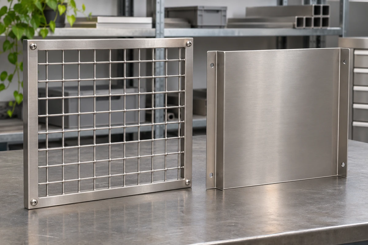
Specify clear opening, reach distance and perimeter gaps
The clear opening is the free dimension between adjacent wires. It can differ from a supplier’s advertised pitch, which is often measured center to center. For a hypothetical grid with a 25 mm pitch and 3 mm round wires, the nominal clear width in that direction is 22 mm before tolerances. That calculation identifies the opening for review. It gives no acceptance distance for a machine. Measure both directions in a rectangular opening and record what happens at bends, cutouts and panel edges.
Treat every route into the danger zone as a separate measurement. A verifier needs to inspect reach through the grid, reach over the top or around the ends, access below the panel, and gaps at doors and service entries. Use the nearest position a moving part can occupy during operation, including any relevant motion or overtravel that the equipment designer identifies. Allow for installed movement or deflection where relevant to maintaining separation. ISO 13857 describes the scope and limits of safety distances. A qualified reviewer must apply the full requirements and any machine-specific rules to the actual layout.[2]
Worked drawing review. A mesh perimeter has an opening under a conveyor that was added after the guard layout was drawn. The grid specification has not changed, but the conveyor opening creates another access route. Mark the opening and the nearest hazard on the current drawing. The equipment safety team can then determine the fixed closure, tunnel or other safeguarding needed and validate the finished arrangement.
Detail the frame, posts and attachments
A good specification identifies the mesh and everything that holds it in place. Establish panel height and width, the welded grid and its wire tolerance, material and finish, frame section, mesh retention, post support and anchors. Record allowances where the support surface is uneven. A shop drawing should show each opening at the door, floor and service penetration, including the gaps that appear when a panel is fitted between posts.
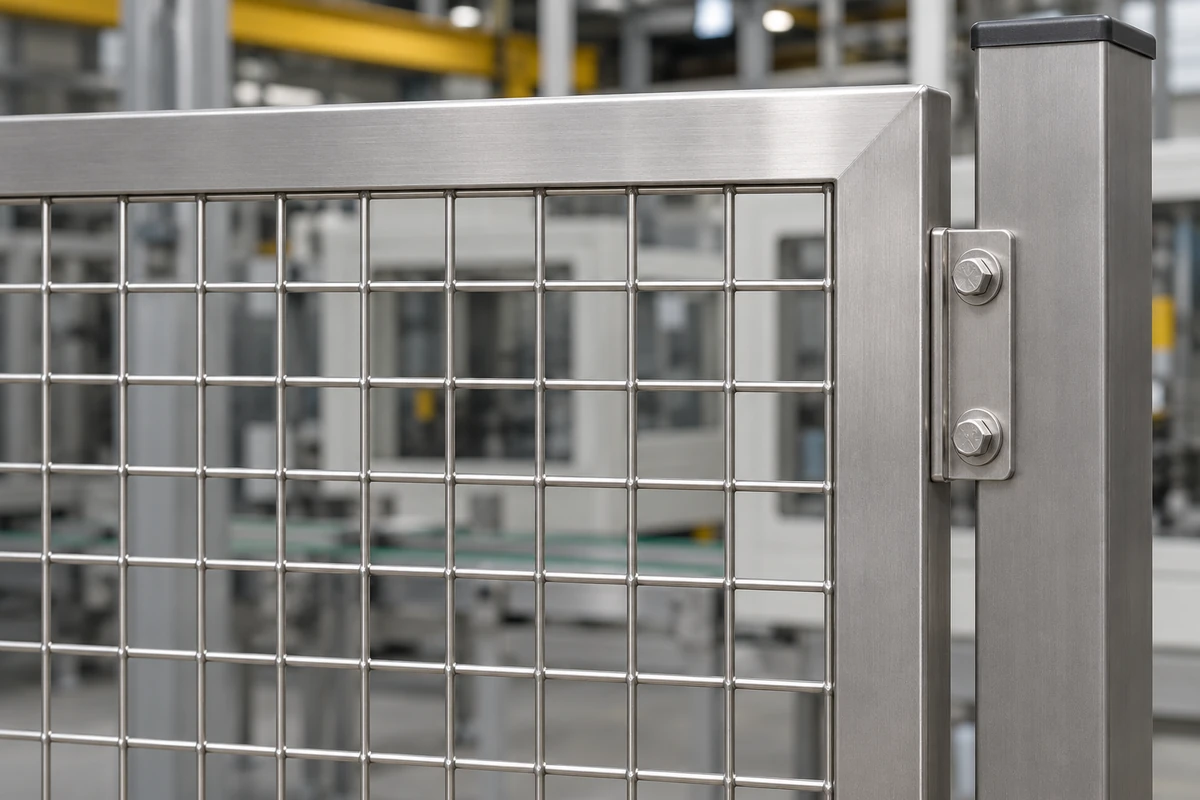
A panel stiffness or impact claim applies to the assembly and conditions used to substantiate it. Ask what was tested, including span, frame, post spacing and anchors. Changing one of those elements can affect the result. When comparing bidders, ask each to identify the exact parts included in its offer and the performance evidence it can supply. ISO 14120 addresses the selection, design and construction of fixed and movable guards.[3]
Plan access doors, cleaning and maintenance
Plot the routes people actually use. An awkwardly positioned or inaccessible service point encourages avoidable guard removal. Let the integrator review door swings, operator visibility, material loading, cleaning access and whether guard locking is required until hazardous movement stops. Record door hardware and controls separately from the mesh on the panel schedule.
Servicing may expose people to hazardous energy even when production has stopped. Verify the isolation procedure with the responsible team and the applicable requirements. Interlocking and lockout are different functions. In the United States, OSHA 1910.147 addresses hazardous energy control for covered servicing and maintenance.[4]
Compare quotations and inspect the installed guard
Ask the buyer and integrator to mark who supplies and verifies each item. A mesh-only order can provide material for a separately designed assembly. A complete guard package may include frames, posts, anchors, access hardware and controls, with different responsibilities for commissioning.
Send XTZ Fence the panel drawings, material and finish, opening and diameter, quantity and frame or edge detail. Include the designer’s requirements for washdown, corrosion or interfaces with the machine. At acceptance, compare the installed panel schedule to the drawings, check fastener engagement and clearance, and have the responsible reviewer validate openings, separation, movable guards and protective functions. Keep the final drawings with the equipment records so a later replacement can preserve the approved conditions.
Frequently asked questions
How large can a machine guard mesh opening be?
Start with the hazard and installed geometry. The permitted opening depends on the applicable requirements, the reach path, the opening shape and the distance to the nearest hazard. Evaluate the mesh and every accessible gap together. An equipment-specific requirement can apply in addition to general guarding rules.
Can a welded mesh panel be used as a guard by itself?
A mesh sheet can be specified as infill. The installed barrier also needs adequate retention, frame and support details, and appropriate protection at doors and openings. Ask for evidence that covers the assembled guard in its intended configuration.
When is a solid shield more appropriate than mesh?
Where debris, sparks or liquid could pass through a grid, specify a shield suitable for the identified hazard. The machine designer determines what containment is required. A hybrid guard can preserve visibility in one part of the enclosure while covering the exposed area.
Should I specify stainless steel for a machine guard?
Consider the cleaning agents, wet service, temperature, mechanical demands and required finish. Stainless steel may make sense where corrosion or cleaning drives the choice. The support and attachment materials deserve the same review as the infill.
Does a guard door always need an interlock?
It depends on the associated hazard and how people use the door. A safety engineer evaluates whether opening can expose hazardous movement and whether an interlock, guard locking or another protective measure is required. Verify the resulting control function before use.
What changes after a machine is relocated?
Review the installed enclosure, its anchor conditions and the actual position of each hazard. A new conveyor opening, changed floor level or revised door position may create a different access route. Update the drawings and repeat the relevant acceptance checks.
Technical sources
- OSHA 29 CFR 1910.212, general machine guarding requirements
- ISO 13857, safety distances for upper and lower limbs
- ISO 14120, design and construction of fixed and movable guards
- OSHA 29 CFR 1910.147, control of hazardous energy