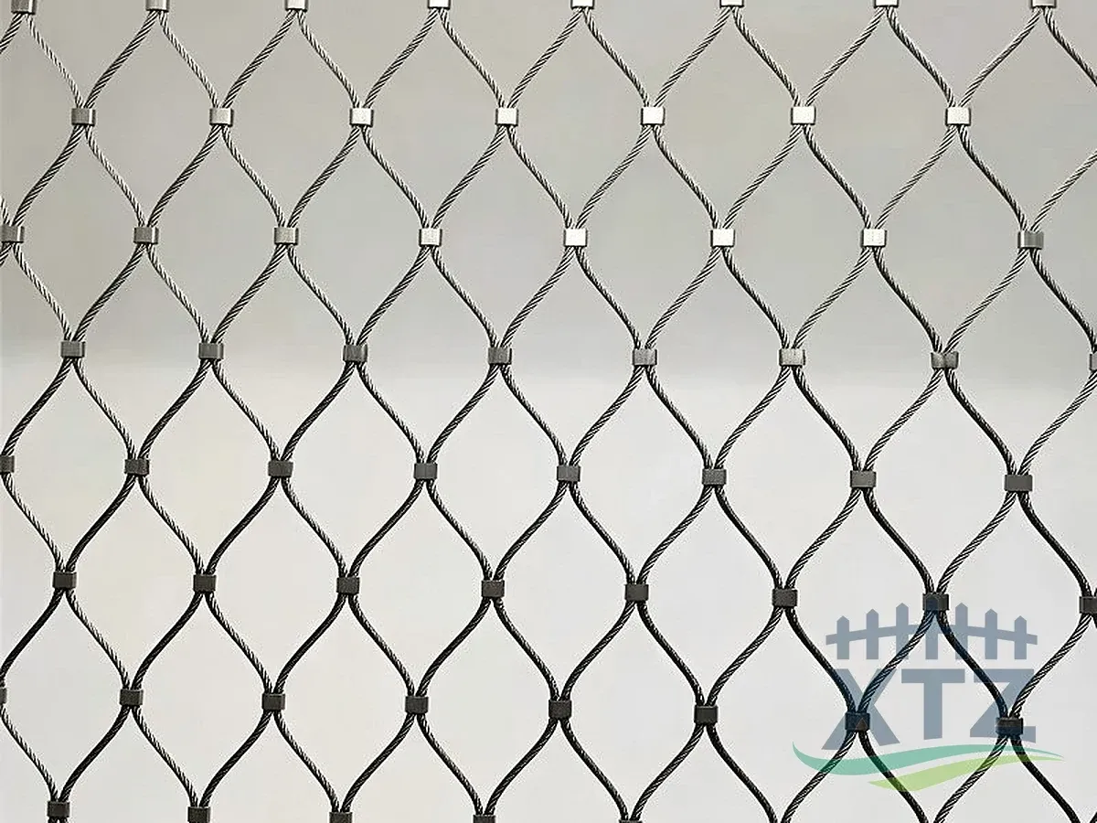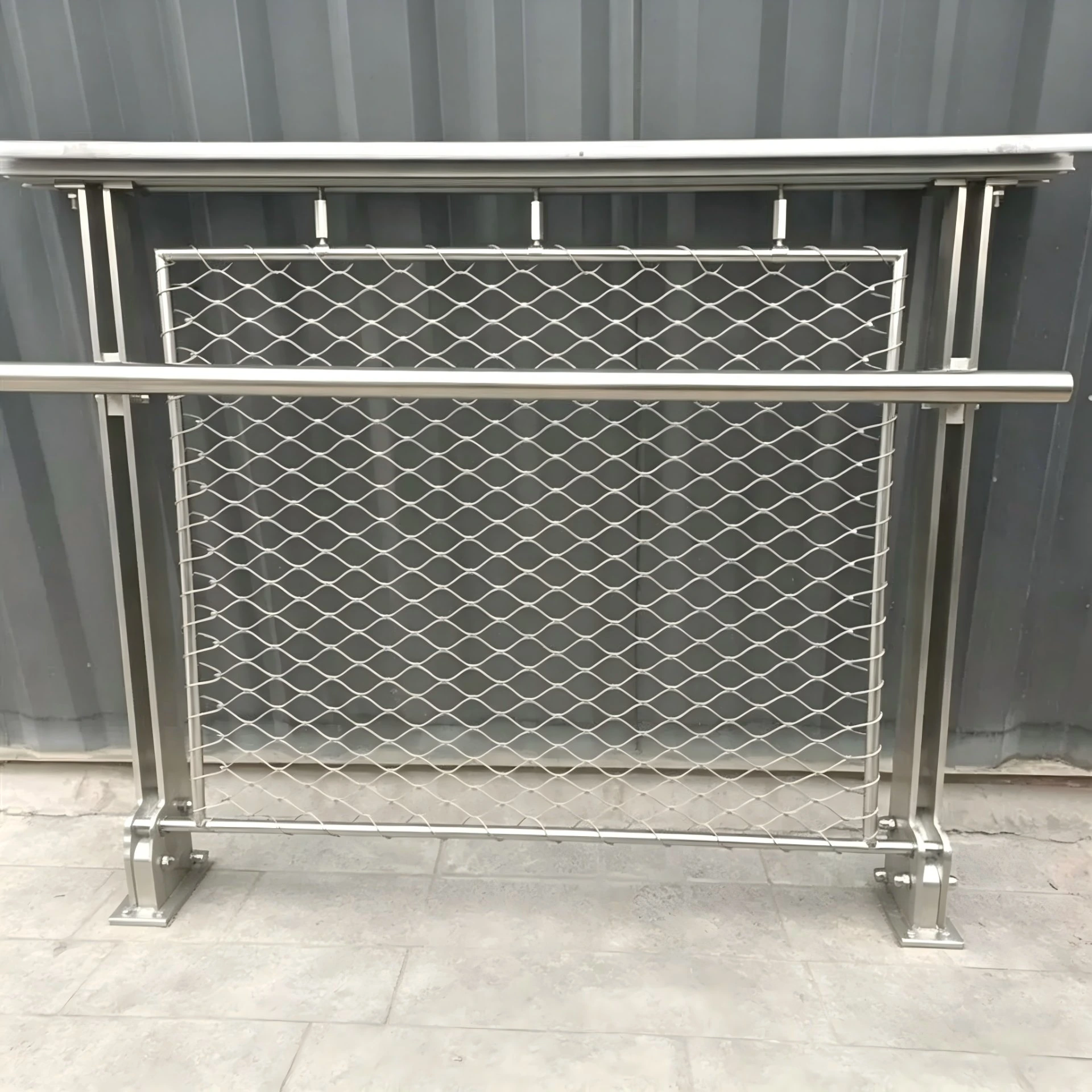
Measure expanded metal in two directions. Start with the short and long diamond pitches, taken between corresponding bond centers. Then measure the clear opening inside the diamond, the width and thickness of a strand, and the overall panel size. Mark which way the diamonds run before you put the sample down.
Identify the face and find a sound diamond
Set the sample on a level surface without pushing it flat. Look along the edge. Raised expanded metal has angled strands and a profile you can see from the side. Flattened metal has passed through rolls, so its face sits closer to one plane. Record the condition you have in hand. A dimension taken from a flattened sample may differ from the listed value for the raised pattern it started as.
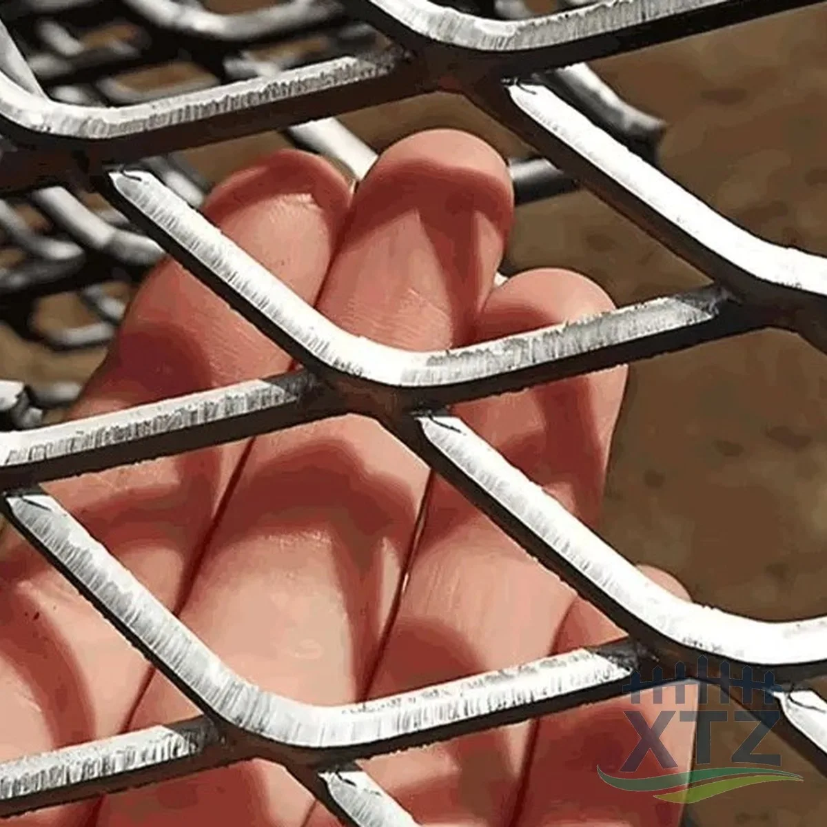
Use a steel rule for repeat spacing, calipers for the opening and strand, and a tape for panel dimensions. Avoid fingers on sheared edges. Pick an undamaged patch away from the frame or cut perimeter. Mark the long diamond axis with removable tape and photograph the face with the rule in the same plane. A second photo taken edge-on will help the supplier identify the profile.
Measure SWD and LWD from bond to bond
A bond, sometimes called a knuckle, is the solid junction where strands meet. Choose a bond at one tip of an intact diamond. Along its long axis, measure from the center of that bond to the center of the bond at the opposite tip. This is the long way of design (LWD). Repeat between the other two tips for the short way of design (SWD). The direction follows the diamond, even when the sheet is turned sideways.
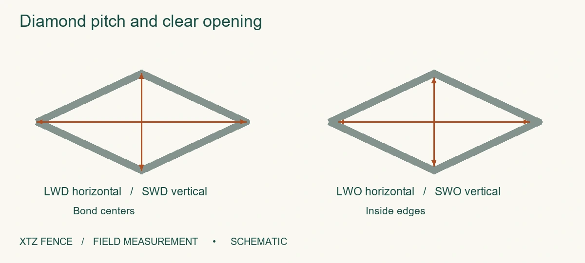
For small diamonds, measure several complete repeats in a straight line and divide by the number of intervals. For example, from the first to the sixth corresponding center there are five intervals. A 150 mm reading gives a 30 mm pitch. Move the rule to another part of the sample and repeat. If the readings differ, record the range and check for local stretching, bent strands or a change in where the rule started.
Measure SWO and LWO inside the opening
Use the inside jaws of the calipers to measure the clear span between opposing inside edges along the short axis (SWO), then along the long axis (LWO). Align the jaws with the axis through the opening center. Near the tip of a narrow diamond, a blunt jaw may stop short. If you cannot reach the endpoints reliably, use a perpendicular face photo with a scale or request a dimensioned drawing. Label an estimated reading as such.
Keep all four values on the same sketch. Two samples with the same pitch can have different clear openings because the strands occupy different amounts of space. On raised mesh, the projected opening viewed square to the face can also differ from what passes through at an angle. If clearance for a real component matters, confirm it on the assembled sample.
Supplier charts may use SWP and LWP for pitch, or SWA and LWA for aperture. Write out “bond center to bond center” or “inside edge to inside edge” next to the numbers so the receiver knows what your tool measured. The illustrated measuring guide shows how these conventions are used for raised and flattened sheets.
Separate strand width, strand thickness and overall depth
| Reading | Where to place the tool | Why it matters |
|---|---|---|
| Strand width | Across one strip, between bonds, perpendicular to its length and on its face. | The wider junction gives a different reading. |
| Strand thickness | Across the two faces of one strip, away from its junction. Use light pressure. | The jaws must follow the local faces of a tilted strand. |
| Overall mesh depth | Measure the envelope from the bottom to the highest point of the raised profile, normal to the panel plane. | This dimension determines how much depth the mesh occupies in a frame. |
If the caliper jaws bridge several tilted strands, you may be reading the overall profile. To check depth on a small flat sample, rest it on a level plate and lay a straightedge gently across the highest points. Measure from the plate to the underside of the straightedge. Check several places. Bow in the panel or a burr on its base can lift the sample and inflate the result.
Record the measured finished thickness in millimeters or inches. If the supplier needs the original sheet gauge, ask for the material record. A coating, flattening pass or worn edge makes a field reading a poor basis for identifying the original stock.
Dimension the sheet and show the installed orientation
Measure the outside cut edges in both directions. On a sketch of the visible face, mark TOP, the long diamond direction and the dimensions parallel and perpendicular to it. A 600 × 900 mm panel can fit its frame either way on paper, yet the diamonds can run in a completely different direction. For several adjacent panels, photograph a joint so the supplier can see whether the rows need to line up.
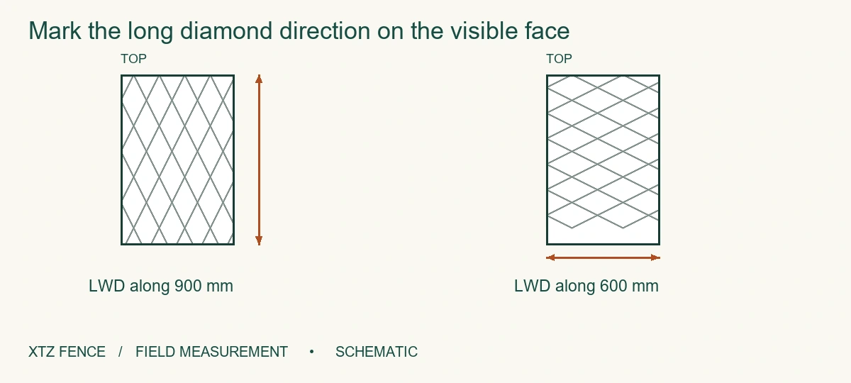
Note whether the edge must end on a row of bonds or can cut through open diamonds. A bond cut can constrain the available finished size because the edge must fall on the repeat. For a framed insert, measure the actual insert separately from the visible opening. Record the allowance under the frame and identify who is supplying the frame. The expanded metal terminology guide illustrates the distinction between bond and random shearing.
A sample record a fabricator can use
Here is an illustrative field note for a replacement screen: “Raised mesh, visible face marked. Five short repeats span 75 mm, five long repeats span 150 mm: SWD 15 mm, LWD 30 mm. Clear opening approximately 11 × 25 mm (short × long). Strand width 2.5 mm, measured thickness 1.5 mm, overall profile depth approximately 4 mm. Insert 600 × 900 mm, LWD parallel to 900 mm edge. See face and edge photos. Confirm grade, finish and acceptable dimensional variation.”
These example readings are observations, not stock specifications. Separate the dimensions that must fit the frame from those that merely help identify the pattern. If a neighboring panel must match, send a retained sample and mark the visible face. When specifying stainless steel expanded metal mesh, add the quantity, environment and required edge treatment so the fabricator can flag any conflict between panel size and bond position.
Frequently asked questions
Does “¾ inch expanded metal” mean a ¾ inch clear opening?
A catalog designation may refer to a nominal pattern size. Check the supplier’s drawing for actual short pitch, long pitch and clear opening. If the application depends on passage through the mesh, specify the clear span and its tolerance explicitly.
Can I calculate the clear opening by subtracting strand width from pitch?
Measure it directly. The strands meet at an angle and widen at the bonds, so subtracting one strand width from the diamond pitch can give a misleading result. If your calipers cannot reach the tips, compare a scaled face photograph with a dimensioned pattern drawing.
What if my old panel is bent or stretched?
Take readings in several sound areas and photograph the damaged section separately. A distorted edge may still tell you how the panel was fixed, but it is a poor reference for the original pitch. If no intact area remains, mark the pattern size as provisional.
Can a photo identify the stainless steel grade?
A photograph helps match pattern and orientation. For alloy identification, use the original order, material documentation or an agreed verification method. Keep “grade unknown” on the enquiry until you have that evidence.
Do these dimensions apply to punched sheet?
For perforated stainless steel mesh, record the punched hole shape, clear size, center spacing and layout. There are no expanded-metal bonds to measure. A close-up of an intact opening helps resolve which product you have.
For a replacement panel, send XTZ Fence the dimensioned sketch with one face photo and one side view. Mark the two or three dimensions the new panel must match exactly; that is often the most useful detail on the drawing.
Recommended Reading
- Expanded Metal Mesh: Raised vs Flattened and Size Guide — Compare profiles after measuring the depth of your sample.
- Expanded metal vs perforated metal: differences and uses — See how a stretched diamond and a punched opening call for different specifications.
- Wire mesh sizes explained: opening, count and wire diameter — Use this guide if the sample has crossing wires and you need to measure wire diameter or mesh count.